Floor-wall connections - watertight joint profiles
Informations for professional construction of building joints along rising building components (such as columns).
Floor-wall connections VA.8...
Floor-wall connection W1
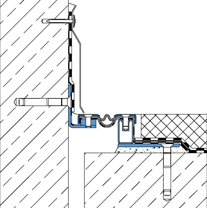
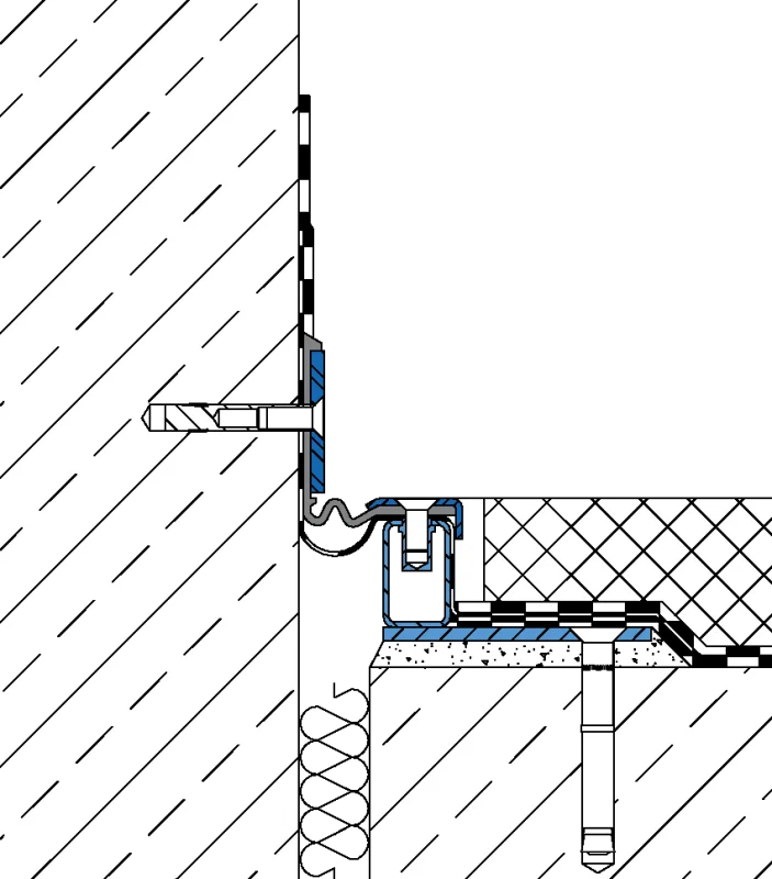
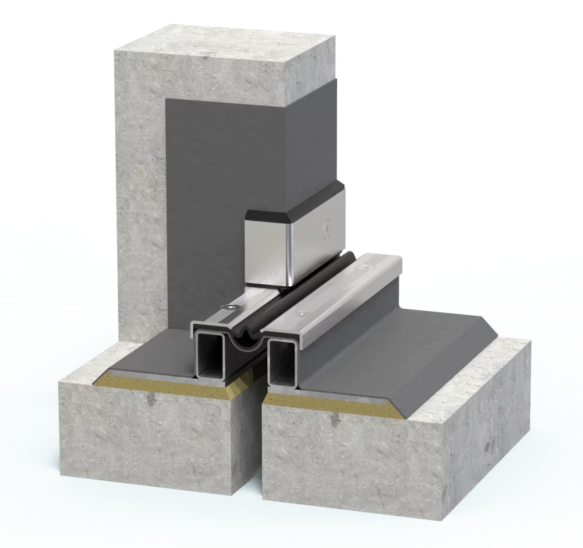
Profile design floor-wall connection W1
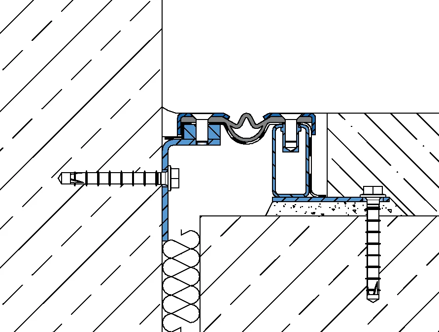
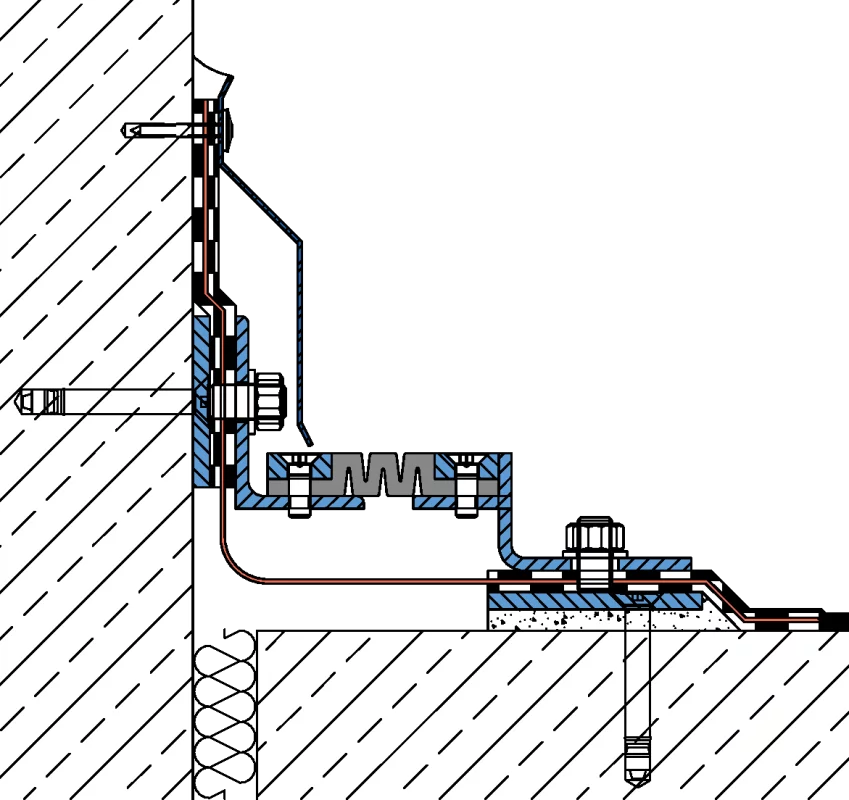
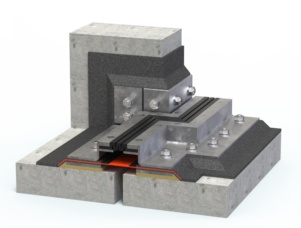
for expansion joints on rising building components with mounting bracket upwards. Raise of the waterproofing membrane to 150 mm above the upper edge of the profile (flashing by arrangement).
System example: VA.8.95/52 F W1
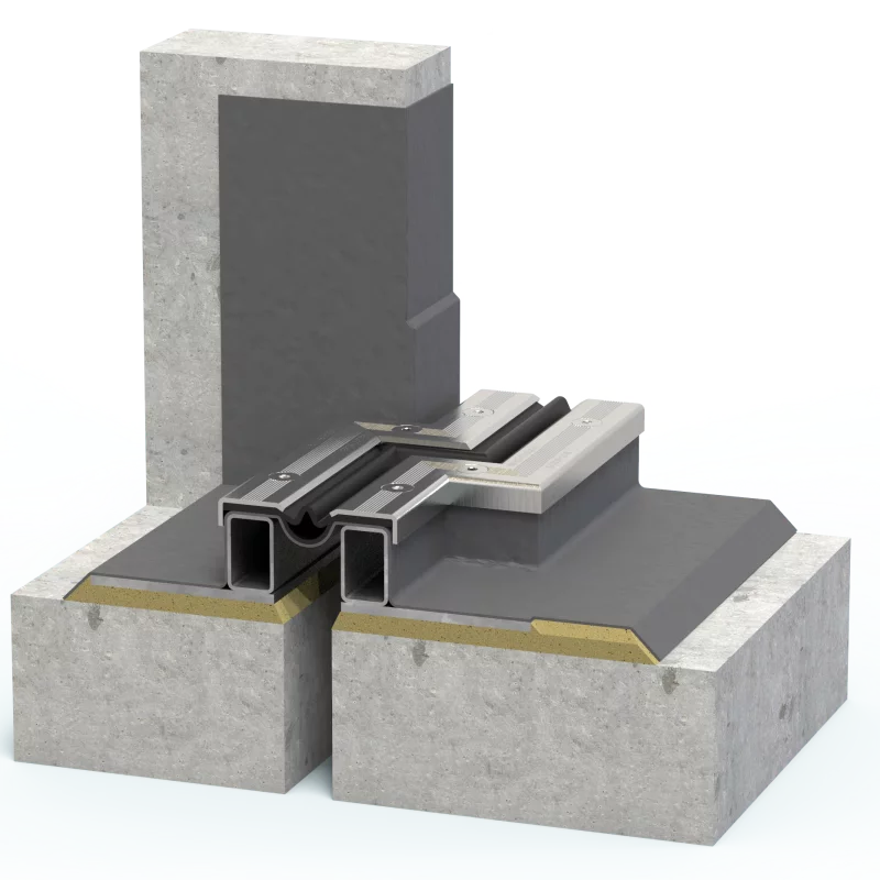
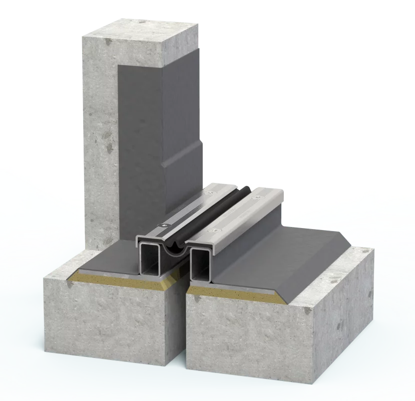
Fitting floor-wall connection W1
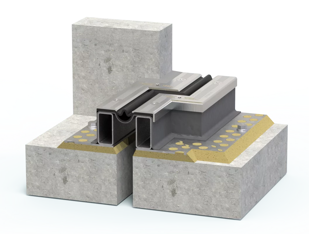
if the expansion joint passes directly on rising building components, two corner pieces are required horizontally at the transition from floor-floor to floor-wall (Z-shaped design).
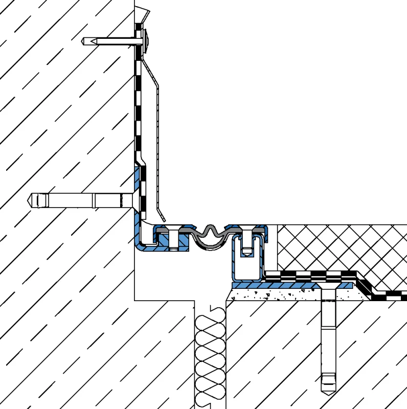
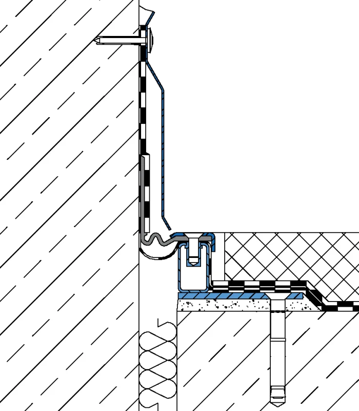
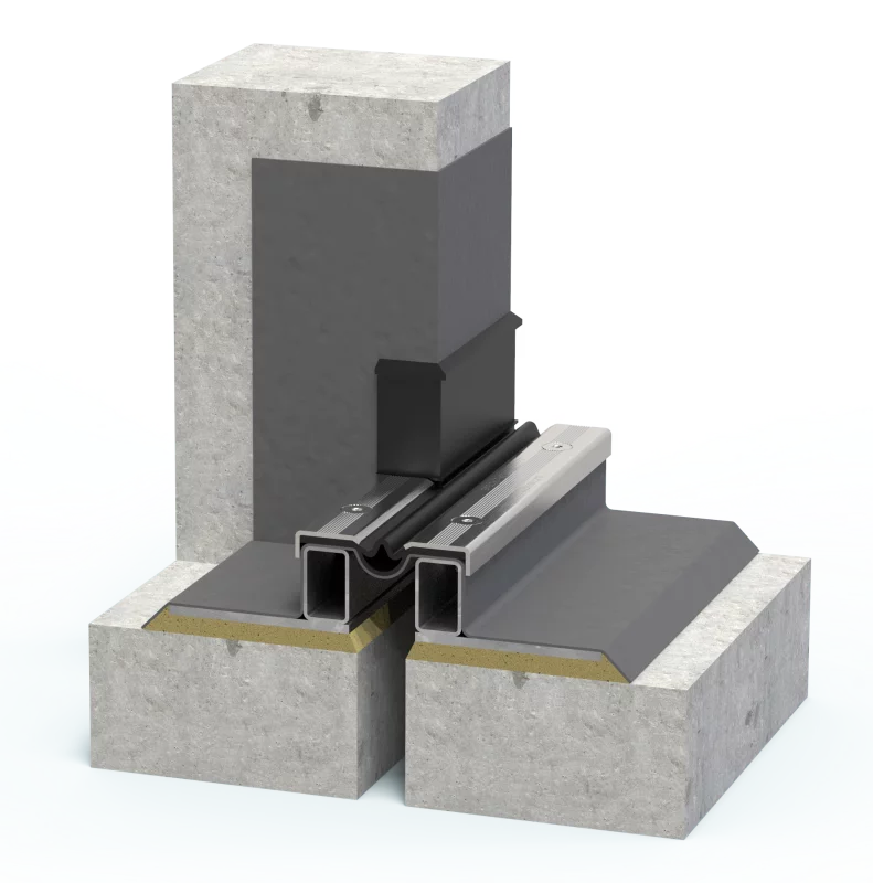
Profile design floor-wall connection W1
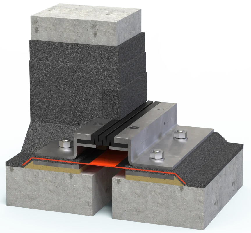
for expansion joints offset to rising building components with mounting bracket upwards. Raise of the waterproofing membrane to 150 mm above the upper edge of the profile (flashing by arrangement).
System example: VA.8.95/52 F W1
Floor-wall connection W2
Profile design floor-wall connection W2
for expansion joints on rising building components with mounting bracket downwards. Installation only possible from profile height of approx. 60 mm.
System example: VA.8.95/60 W2
Floor-wall connection W3
Profile design floor-wall connection W3
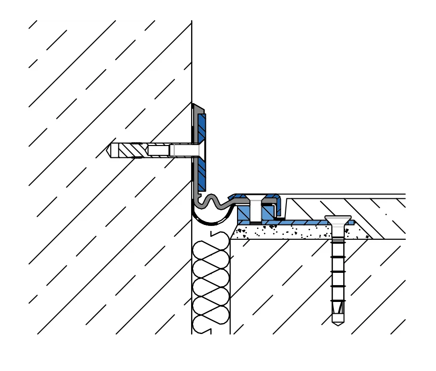
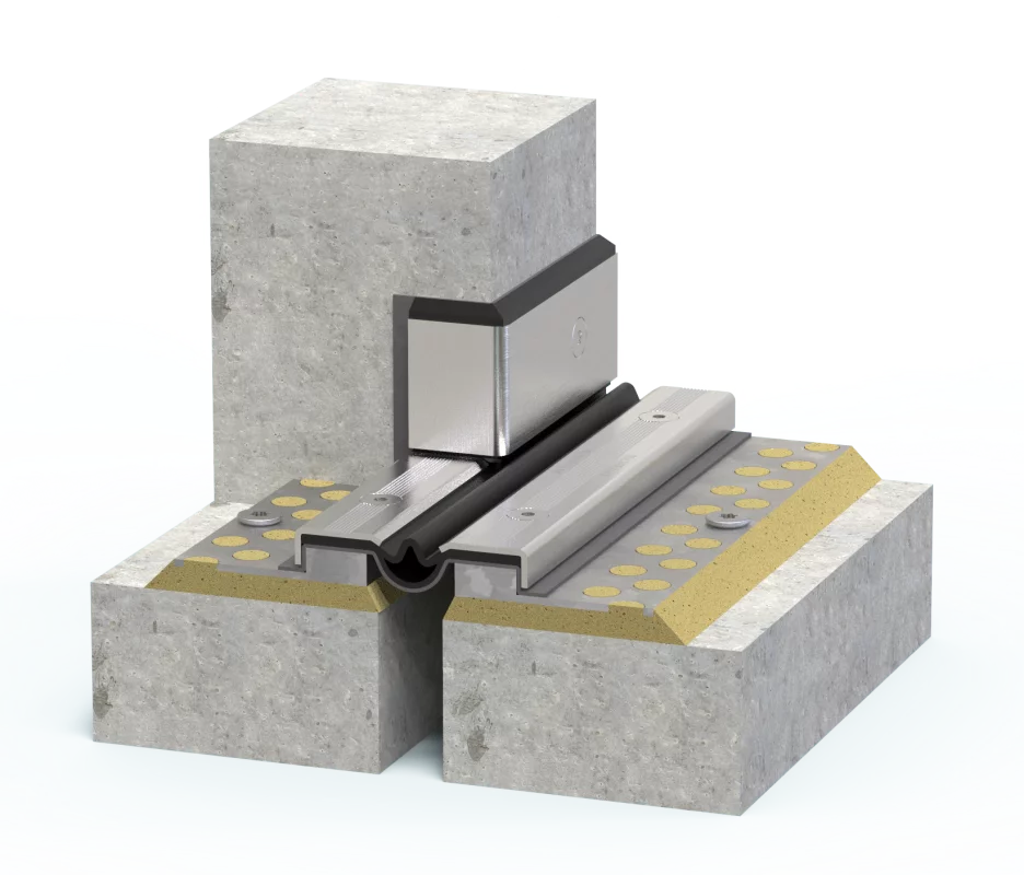
for expansion joints on rising building components with mounting bracket upwards. Raise of the waterproofing membrane to 50 mm above the upper edge of the profile.
System example: VA.8.95/20 W3
Floor-wall connection W4
Profile design floor-wall connection W4
for expansion joints on rising building components with mounting bracket upwards. Raise of the waterproofing membrane to 150 mm above the upper edge of the profile.
System example: VA.8.95/52 F W4
Floor-wall connection W5
Profile design floor-wall connection W5
for expansion joints on rising building components with mounting bracket upwards. Raise of the waterproofing membrane to 150 mm above the upper edge of the profile (flashing by arrangement).
System example: VA.8.95/52 F W5
Floor-wall connection BBF...
Floor-wall connection W1
Profile design floor-wall connection W1
for expansion joints on rising building components with mounting bracket upwards. Raise of the waterproofing membrane to 150 mm above the upper edge of the profile (flashing by arrangement).
System example: BBF124/55 W1
